From Packets to Protocols
Abstract
This project will do a deep dive into networking and why it is so important in the trading environment to understand it thoroughly. In high performance trading systems, networking is not just an implementation detail. It is a core component that directly affects latency, determinism, reliability, and ultimately profitability.
Because of the breadth and depth of the topic, I decided to split the discussion into two separate articles for better clarity and structure.
In this first part, we focus on the theoretical foundations of networking. We progressively build from core concepts such as IP addressing, ports, sockets, encapsulation, and the TCP/IP model. The objective is to understand how data actually moves across the network stack, layer by layer, and what truly happens when an application sends a message. This section establishes the structural framework necessary to reason about performance, latency, and system behavior.
In the second part, we will dive deeply into the transport layer, with a detailed analysis of TCP and UDP. We will examine connection lifecycle, reliability mechanisms, congestion control, flow control, head-of-line blocking, and the practical trade-offs between TCP and UDP in trading systems.
In the third part, we will move from theory to practice. We will analyze the practical implementation of a WebSocket client using the Boost.Beast framework in C++ for my Deribit API client. We will connect transport layer concepts to real code, discuss architectural decisions such as threading, non-blocking I/O, lock-free queues, rate limiting, and backpressure management, and show how networking abstractions map onto concrete implementation choices in a production-grade trading system.
Part 1: Networking basics
Part 2: TCP and UDP in trading systems
Part 3: WebSocket implementation
Networking Fundamentals
What Is a Network? A network is a system of interconnected devices that exchange data using a shared set of communication protocols. These devices can be computers, servers, routers, switches, or any hardware capable of sending and receiving digital information.
At a high level, networks can be classified as:
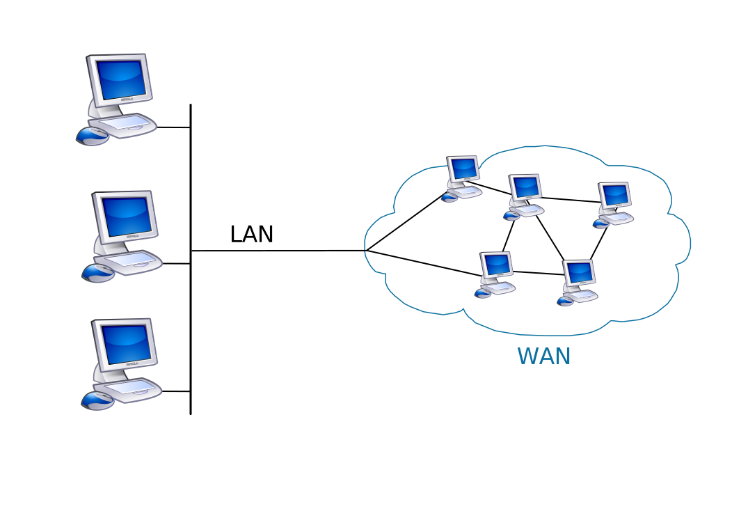
- LAN (Local Area Network)
A network covering a limited geographic area such as a home, office, or data center. LANs are typically high bandwidth and low latency.
- WAN (Wide Area Network)
A network that spans large geographic areas such as cities, countries, or continents. The internet itself is the largest example of a WAN.
In trading environments, internal matching engines and market data systems often operate inside LANs for minimal latency, while exchange connectivity may traverse WAN infrastructure.
Packets vs Frames
Data does not move across a network as a continuous abstract stream. Even though applications perceive communication as a stream of bytes, the underlying network infrastructure transmits information in discrete, structured units. These units differ depending on the layer of the network stack being considered.
To understand networking properly, it is important to distinguish between frames and packets, and to understand how they relate to each other.
Frames
A frame is the data unit at the data link layer. It is responsible for communication within a single local network segment, such as an Ethernet network inside a data center or office.
An Ethernet frame typically contains:
- A destination MAC address
- A source MAC address
- A type field indicating the encapsulated protocol
- A payload
- An error detection field such as a Frame Check Sequence

The MAC address identifies a specific network interface card. Unlike IP addresses, MAC addresses are not used for routing across the internet. They are only meaningful within a local network segment.
Frames operate at the local level. When a machine sends data to another machine on the same LAN, it sends an Ethernet frame directly addressed to the target MAC address. If the destination is outside the local network, the frame is addressed to the local router, which then forwards the data onward.
Frames are removed and recreated at every hop across routers. They do not travel unchanged across the entire internet.
Packets
A packet is the data unit at the network layer. In most practical systems, this refers to an IP packet.
An IP packet contains:
- A source IP address
- A destination IP address
- Routing related fields such as TTL
- A payload
The IP address allows routers to determine where the packet must go next. Unlike frames, packets are designed to travel across multiple networks.
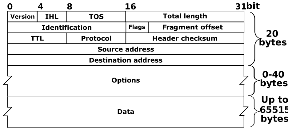
Each router examines the destination IP address and forwards the packet closer to its final destination.
Packets are logical routing units. They persist across hops, even though the surrounding frames change at each link in the route.
IP Addressing
An IP address is a logical identifier assigned to a device participating in a network. It allows that device to be located and reached by other devices using the Internet Protocol.
Unlike MAC addresses, which identify a network interface at the hardware level, IP addresses operate at the network layer and are used for routing across multiple networks. Routers examine IP addresses to determine where data should be forwarded next.
An IP address does not represent a physical location. It represents a logical position within a network topology.
IPv4
The most common IP address used is IPv4, it is the fourth version of the Internet Protocol and remains widely deployed today. It uses a 32 bit address space, which means it can represent 2^{32} possible combinations.
IPv4 addresses are written in dotted decimal notation, such as:
192.168.1.10
Each of the four numbers represents 8 bits, ranging from 0 to 255.
Originally, 2^{32} addresses seemed sufficient. However, with the exponential growth of devices connected at the network layer the available IPv4 address space was exhausted.
This scarcity led to the widespread adoption of NAT, which allows multiple private devices to share a single public IPv4 address. Despite its limitations, IPv4 remains dominant because of legacy systems and compatibility requirements.
IPv6
IPv6 was introduced to address the limitations of IPv4, primarily address exhaustion. It uses a 128 bit address space, allowing 2^{128} possible addresses. This number is astronomically large, effectively eliminating the risk of address scarcity!
IPv6 addresses are written in hexadecimal notation and separated by colons, for example:
2001:0db8:85a3:0000:0000:8a2e:0370:7334
The format is longer but more scalable and flexible.
Beyond increasing address capacity, IPv6 introduces several architectural improvements:
- Simplified header structure for more efficient routing
- Elimination of broadcast in favor of multicast
- Built in support for stateless address autoconfiguration
- Improved hierarchical addressing for aggregation
One major consequence of IPv6’s large address space is that NAT is no longer necessary in many deployments. Each device can have a globally routable address. With this setup every device connected to the network layer is accessible from anywhere else of the network and this could be a security issue! Indeed, NAT is still sometimes used for policy or security reasons.
Public vs Private IP Addresses
An IP address determines whether a device can be reached globally or only within a local network. The distinction between public and private addressing is fundamental to understanding how connectivity is established across the internet.
When a trading system connects to an exchange, the path taken and the visibility of the endpoints depend heavily on whether the involved addresses are public or private.
Public IP Addresses
A public IP address is globally unique and routable across the public internet.
This means:
- No two devices on the public internet share the same public IP at the same time.
- Routers across the world know how to forward traffic to that address.
- The address is reachable from any other internet-connected host, assuming firewall rules permit it.
Public IP addresses are allocated by regional internet registries and typically assigned by Internet Service Providers or cloud infrastructure providers.
When you access an exchange API, such as a crypto exchange endpoint, you are connecting to a public IP address. That address is advertised through global routing protocols such as BGP (Border Gateway Protocol), allowing packets from anywhere in the world to find their way to the exchange’s data center.
Public IPs have several characteristics:
- They are visible to the entire internet.
- They are subject to scanning and attack attempts.
- They must be protected using firewalls, access control lists, and rate limiting.
- They often sit behind load balancers or reverse proxies.
In professional trading environments, public IP exposure is tightly controlled. Exchanges may restrict access to specific IP ranges, and trading firms may whitelist only certain source addresses.
Private IP Addresses
Private IP addresses are reserved for use inside internal networks and are not routable over the public internet.
The reserved ranges defined by RFC 1918 are:
- 10.0.0.0/8
- 172.16.0.0/12
- 192.168.0.0/16
These address blocks can be reused in different private networks without conflict because they are never propagated into global internet routing tables.
For example:
- Your laptop at home might have 192.168.1.10.
- A trading server inside a data center might have 10.0.5.20.
- A completely unrelated corporate network might also use 10.0.5.20 internally.
Because private IPs are not globally routable, routers on the internet will discard packets destined for them. This is a security feature and a design choice that enables network isolation!
Private addressing allows organizations to:
- Build large internal networks without consuming public IP space.
- Segment infrastructure logically.
- Isolate sensitive systems such as trading engines and risk management servers.
In a trading firm, internal systems such as:
- Matching simulators
- Strategy engines
- Risk aggregation services
often communicate over private IP networks within a controlled data center environment.
NAT (Network Address Translation)
Network Address Translation is the mechanism that bridges private and public addressing.
As we said above, private IP addresses are not routable on the public internet, a translation layer is required when a private host wants to communicate externally. This is why NAT is used, is a mechanism that works as a firewall between the two layers.
Example

Consider a machine inside a private network:
- Private IP: 192.168.1.15
- It wants to connect to an exchange at 203.0.113.10 on port 443.
The outbound packet initially looks like:
- Source IP: 192.168.1.15
- Source port: 123
- Destination IP: 203.0.113.10
- Destination port: 20200
When this packet reaches the local router performing NAT, the router:
- Replaces the source IP (192.168.1.15) with its own public IP.
- Potentially rewrites the source port to maintain uniqueness.
- Stores a mapping in a translation table.
The mapping might look like:
PublicIP:50000 → 192.168.1.15:53021
Now the packet leaving the network has:
- Source IP: PublicIP
- Source port: 50000
- Destination IP: 203.0.113.10
- Destination port: 443
When the exchange responds, the response arrives at PublicIP:50000. The NAT device consults its translation table and forwards the packet back to 192.168.1.15:53021.
To the external server, the internal host is invisible. Only the public IP is visible.
Sockets
Up to this point, we have described how machines are identified using IP addresses, how services are differentiated through ports, and how packets are routed across networks. However, one fundamental question remains: how does an application actually use this infrastructure?
An application does not construct Ethernet frames. It does not manually populate IP headers. It does not manage retransmissions or congestion windows. Instead, it interacts with the operating system through a socket.
A socket is the abstraction that bridges user space applications and the kernel networking stack. It is the mechanism through which a program sends and receives data over a network.
At the conceptual level, a socket represents one endpoint of a bidirectional communication channel between two processes. When a client connects to a server over TCP (more on this protocol later), each side owns a socket. Those two sockets are logically connected by the network stack and together form a communication channel. But this high level description hides the real complexity.
Inside the operating system, a socket is a kernel managed object. When a program creates a socket, the kernel allocates internal data structures that maintain all information necessary to handle communication. This includes local and remote addresses, port numbers, protocol state, and memory buffers used to temporarily store outgoing and incoming data.
For a TCP socket, the kernel maintains additional state such as sequence numbers, acknowledgement numbers, congestion control parameters, retransmission timers, and connection state transitions like SYN_SENT or ESTABLISHED. In other words, a TCP socket is not just a pipe. It is a state machine implemented inside the kernel.
When an application writes data into a socket, it is not directly sending packets onto the wire. It is writing bytes into a kernel buffer. The kernel then segments this data into TCP segments, wraps those segments inside IP packets, wraps those packets inside Ethernet frames, and hands them to the network interface card for transmission. The reverse happens on reception: frames are received by the NIC, processed by the kernel, reassembled into segments, placed into the receive buffer, and finally made available to the application as a stream of bytes.
From the perspective of the application, all of this complexity collapses into a simple interface: read and write.
Binding and Connection Identity
A socket becomes meaningful only once it is associated with an IP address and a port. On the server side, a socket is bound to a local address and port, such as 203.0.113.10:443. On the client side, when a connection is initiated, the operating system automatically assigns a source port.
Once the connection is established, it is uniquely identified by four values: source IP, source port, destination IP, and destination port. This four tuple allows the kernel to distinguish between multiple simultaneous connections, even if they are between the same two machines.
This design enables a single server to handle thousands of concurrent clients. Each client connection corresponds to a distinct socket with its own state and buffers, even if all connections target the same IP and port!
The File Descriptor Model in Unix Systems
In Unix-like operating systems, the design philosophy is that everything is treated as a file. This includes regular files on disk, pipes, devices, and network sockets.
When a socket is created, the kernel returns a file descriptor, which is simply an integer. This integer is an index into a per-process table that maps file descriptors to open kernel objects. Behind that integer lies the full socket structure with its buffers and protocol state.
This design allows a uniform interface for I/O. The same system calls used to read from a file can be used to read from a socket. This uniformity is what enables multiplexing mechanisms such as select, poll, and epoll. These mechanisms monitor file descriptors and notify the application when data is ready or when buffer space becomes available.
Because sockets are integrated into this file descriptor model, they can participate naturally in event-driven architectures. This becomes essential in high performance systems where thousands of connections must be managed efficiently.
Blocking and Non Blocking Modes
Sockets can operate in blocking or non blocking mode, and this distinction has deep architectural consequences.
In blocking mode, when an application calls read on a socket and no data is available, the operating system suspends the calling thread until data arrives. Similarly, if the application attempts to write data and the send buffer is full, the thread waits until space becomes available.
This model is simple and intuitive. Each operation either completes successfully or waits until it can. However, blocking I/O ties the lifetime of a thread to the availability of network events. In systems with many connections, this can lead to large numbers of threads, frequent context switches, and increased memory usage.
In non blocking mode, operations return immediately. If no data is available, the call fails with an indication that the operation would block. The application must then rely on readiness notification mechanisms such as epoll or kqueue to know when the socket becomes readable or writable.
This enables event-driven programming. Instead of dedicating one thread per connection, a small number of threads can manage many sockets by reacting to readiness events. This significantly reduces context switching and improves scalability.
High performance trading systems often rely on non blocking or asynchronous I/O. Even when using higher level libraries such as Boost.Asio or Boost.Beast, the underlying implementation is built on non blocking sockets and an event loop!
Why This Matters in Trading Infrastructure
Every order sent to an exchange and every market data update received flows through a socket. The behavior of that socket determines how data is buffered, when backpressure occurs, and how the system reacts under load.
If the receive buffer fills up because the application cannot process messages quickly enough, data may accumulate in the kernel. If the send buffer fills up, write operations may block or fail. If many sockets are opened without proper resource management, the system may exhaust file descriptors.
At a superficial level, networking in a trading system might appear to be a matter of calling connect and write. At a deeper level, it involves interacting with kernel-managed state machines, memory buffers, and scheduling mechanisms that directly influence performance.
OSI vs TCP/IP Model
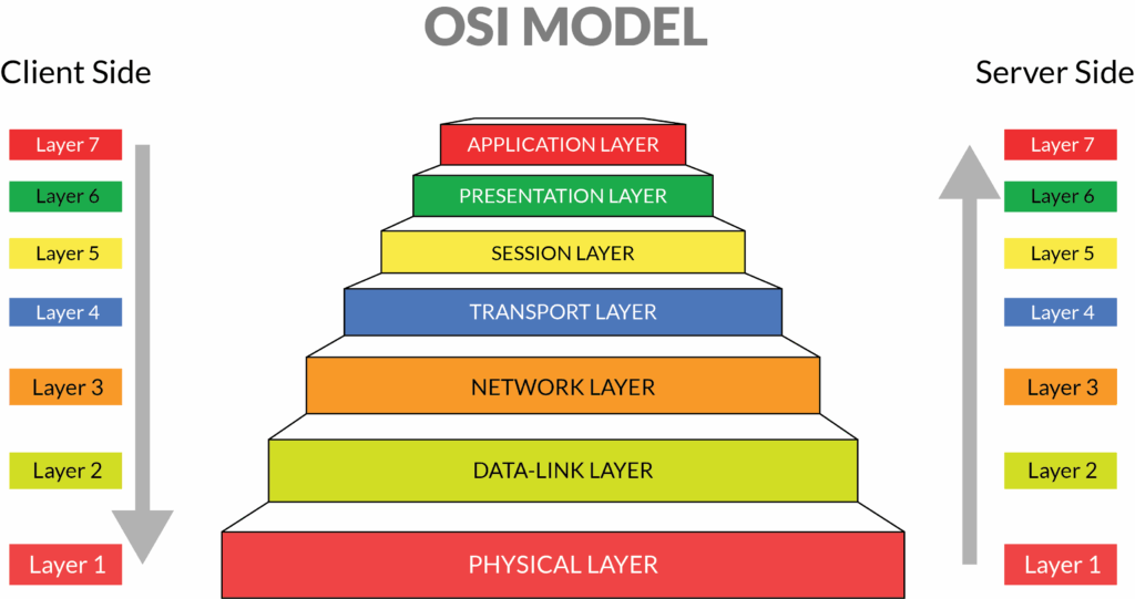
Networking is often introduced through layered models that separate responsibilities into conceptual blocks. These models are not physical implementations but abstractions that help engineers reason about complex distributed systems.
The most commonly referenced framework is the OSI model. It divides networking into seven layers, starting from physical signal transmission and ending at application-level logic. The OSI model is useful because it forces a clean separation between responsibilities such as routing, reliability, formatting, and session management.
However, real-world operating systems do not implement networking according to the OSI model literally. Instead, modern networking stacks are built around a simpler and more practical structure known as the TCP/IP model.
The TCP/IP model organizes networking into four layers:
- Link layer
- Internet layer
- Transport layer
- Application layer
This model reflects how networking is actually implemented in Linux, BSD, and Windows.
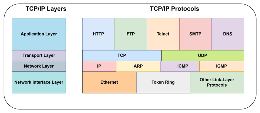
The diagram shows two complementary views of the TCP/IP model.
On the right, we see the concrete protocols that operate at each of these layers. This mapping is essential because it connects abstraction to implementation. Unlike the seven-layer OSI model, the TCP/IP model is more practical. It reflects how networking is actually implemented in modern systems.
Network Interface Layer
At the bottom of the diagram we find the Network Interface Layer. The protocols shown here include:
- Ethernet
- Token Ring
- Other link-layer protocols
This layer is responsible for communication within a single local network segment. It handles the mechanics of transmitting data between two directly connected devices.
Its responsibilities include:
- Framing data into Ethernet frames
- Adding source and destination MAC addresses
- Detecting transmission errors
- Interacting with the physical network interface card
When an IP packet is ready to leave a machine, it must be placed inside an Ethernet frame before it can be transmitted over the wire. The Network Interface Layer is responsible for this encapsulation.
It is important to understand that this layer operates locally. Ethernet frames do not travel unchanged across the internet. Every time a packet reaches a router, the existing frame is removed and a new frame is constructed for the next hop!
In low-latency trading environments, this layer becomes particularly important. The performance of the network interface card, driver configuration, interrupt moderation, and buffer sizing can all influence end-to-end latency. Even though most application developers rarely think about Ethernet directly, this layer ultimately determines how bits leave the machine.
Network Layer
Above the Network Interface Layer sits the Network Layer. The protocols shown in the diagram are:
- IP
- ARP
- ICMP
- IGMP
The central protocol here is IP, the Internet Protocol.
IP provides logical addressing and routing. It defines how packets move across networks from source to destination. Each IP packet contains source and destination IP addresses, and routers use this information to determine where the packet should be forwarded next.
Unlike Ethernet frames, IP packets are designed to traverse multiple networks. As the packet moves through routers, the link-layer framing changes at every hop, but the IP packet itself remains logically consistent.
Other protocols in this layer serve supporting roles:
- ARP resolves IP addresses to MAC addresses within a local network. When a machine knows the destination IP but does not know the corresponding MAC address, it uses ARP to discover it.
- ICMP is used for control and diagnostic purposes. For example, the ping command relies on ICMP to measure reachability and round-trip time.
- IGMP manages multicast group membership, allowing multiple hosts to subscribe to the same multicast stream. This is particularly relevant in market data distribution systems that use multicast feeds.
The Network Layer provides best-effort delivery. It does not guarantee that packets will arrive, nor does it ensure they arrive in order. Its role is routing, not reliability.
Transport Layer
The Transport Layer sits above IP and is one of the most critical layers for trading systems. The diagram shows two main protocols at this layer:
- TCP
- UDP
This layer is responsible for delivering data between specific processes running on different machines. It introduces the concept of ports, which allow multiple applications to communicate simultaneously over the same IP address.
When an application creates a socket, it is interacting with the Transport Layer through the operating system kernel.
TCP provides reliable, ordered, congestion-controlled communication. It is a connection-oriented protocol, meaning that it establishes a connection before data is exchanged.
Internally, TCP maintains a state machine inside the kernel. It manages:
- Sequence numbers
- Acknowledgements
- Retransmissions
- Congestion windows
- Flow control windows
- Connection states
If a packet is lost, TCP detects the loss and retransmits it. If the network becomes congested, TCP reduces its transmission rate.
This reliability makes TCP ideal for:
- Order submission
- REST APIs
- WebSocket connections
- FIX sessions
In a trading system, when you send an order via a WebSocket over TLS over TCP, the reliability guarantees ultimately come from TCP.
UDP is much simpler. It is connectionless and does not provide reliability or ordering guarantees.
Each UDP datagram (more on this later) is independent. The protocol does not track state, retransmit lost packets, or implement congestion control.
This simplicity results in lower overhead and lower latency in certain scenarios.
In trading infrastructure, UDP is often used for market data feeds, especially multicast feeds. Missing a market data packet is acceptable because the next update may contain sufficient information to recover state. Missing an order is not acceptable, which is why order flow uses TCP.
Application Layer
At the top of the stack is the Application Layer. The diagram shows protocols such as:
- HTTP
- FTP
- Telnet
- SMTP
- DNS
These protocols define the meaning of the data being transmitted. They do not define how it is transmitted reliably. That responsibility belongs to the Transport Layer.
Example:
HTTP defines request and response semantics. It specifies headers, methods, and status codes. It does not define how lost packets are retransmitted.
DNS resolves domain names to IP addresses. It often runs over UDP but can fall back to TCP when necessary.
In trading systems, the Application Layer includes:
- WebSocket APIs
- REST APIs
- FIX protocol
- Binary exchange-specific protocols
These protocols define message formats, authentication schemes, and session rules. They rely on the Transport Layer to actually deliver the data.
How the Layers Interact in Practice
To make this concrete, consider a WebSocket message sent from a trading application.
| Application Layer | System constructs a JSON message formatted according to the exchange’s API specification |
| Transport Layer | TCP segments the data and ensures it will be delivered reliably and in order |
| Network Layer | IP determines how the packet will travel across routers to reach the exchange’s data center |
| Network Interface Layer | Packet is placed inside an Ethernet frame and transmitted over the physical medium |
On the receiving side, the process is reversed. Each layer removes its corresponding header and passes the payload upward.
Each layer has a specific responsibility.
How Data Actually Travels
Up to this point, we have described layers conceptually. Now we move from abstraction to reality.
When a trading application sends a message to an exchange, the data does not magically “go over the network”. It passes through a precise sequence of transformations, each layer adding its own metadata and responsibilities.Let us walk through what actually happens when your trading system sends a WebSocket message.
Assume your C++ Deribit client sends the following JSON-RPC message over a secure WebSocket connection:
{
  "jsonrpc": "2.0",
  "id": 5275,
  "method": "private/buy",
  "params": {
    "instrument_name": "ETH-PERPETUAL",
    "amount": 40,
    "type": "market",
    "label": "market0000234"
  }
}From the perspective of your code, this is just a string. You may construct it using a JSON library and then call:
ws.write(net::buffer(order_json));But the moment this call is made, a multi-layer transformation begins inside the operating system and the networking stack.
From your application’s perspective, this is simply structured data serialized into a string. In memory, it is just a contiguous array of bytes. It has meaning only because both client and exchange agree on the JSON-RPC protocol.
At this stage, the message has semantic meaning. It represents a market buy order for 40 contracts of ETH-PERPETUAL. It carries identifiers, routing logic within the exchange, and business intent.
Structuring the Message
Because Deribit uses WebSocket, the JSON message is not written directly into TCP. It is first encapsulated inside a WebSocket frame. The WebSocket protocol defines how application messages are packaged. It adds a small header containing:
- Frame type (text in this case)
- Payload length
- Flags indicating whether this is a final frame
- A masking key for client-to-server messages
The masking mechanism exists for security reasons defined in the WebSocket specification. Every byte of the payload is XOR-masked before transmission. (cross-protocol attack is an example)
At this level, message boundaries are preserved. The WebSocket protocol treats your JSON object as one logical message. However, the data is still plaintext. There is no confidentiality yet. Intermediaries could inspect the payload if encryption were not applied.
Encryption and Integrity
In real trading systems, WebSocket connections are secured using TLS (Transport Layer Security). This means that before the WebSocket frame is handed to TCP, it passes through the TLS layer.
TLS transforms the WebSocket frame into a TLS record. This process involves:
- Encrypting the payload
- Adding integrity protection using authenticated encryption
- Attaching a record header
- Generating an authentication tag
After this step, the payload is no longer readable without the session keys negotiated during the TLS handshake (it happens when connection is estabilished). From this point onward:
- Routers cannot inspect your JSON.
- Only the exchange server with the correct private key can decrypt the content.
- Any modification in transit would be detected.
TLS relies entirely on TCP for reliable byte delivery. TLS assumes the underlying transport is ordered and lossless. If TCP stalls due to congestion or packet loss, TLS cannot progress. If TCP retransmits, TLS must wait.
Reliability and Flow Control
Now the encrypted TLS record enters the TCP layer inside the operating system kernel.
This is where the stream abstraction begins.
Your application wrote a buffer. TCP sees only a sequence of bytes. It has no awareness of JSON, WebSocket frames, or TLS records. TCP performs several critical functions:
- Divides the byte stream into segments according to the Maximum Segment Size negotiated during connection setup.
- Assigns sequence numbers to every byte.
- Maintains retransmission timers.
- Manages congestion control through algorithms such as slow start and congestion avoidance.
- Enforces flow control using the receive window mechanism.
If the encrypted payload is small enough, it may fit into a single TCP segment. If it exceeds the maximum segment size, TCP splits it across multiple segments. Each segment carries:
- Source and destination ports
- Sequence and acknowledgement numbers
- Control flags
- Window size information
At this layer, reliability is enforced. If a segment is lost, the receiver does not acknowledge it. The sender detects the missing acknowledgement and retransmits the data.
Routing Across Networks
Each TCP segment is then encapsulated into an IP packet. The IP header adds:
- Source IP address
- Destination IP address
- Time To Live field
- Protocol identifier indicating TCP
- Fragmentation-related fields
The IP layer is responsible for routing. Routers examine the destination IP address and forward the packet toward the exchange’s data center. The IP layer does not provide reliability, it simply forwards packets based on routing tables.
If a router drops a packet due to congestion, IP does nothing. It is TCP’s responsibility to detect and recover from the loss.
Physical Transmission
Finally, the IP packet is wrapped inside an Ethernet frame. The completed frame is placed into the NIC transmit queue (out of the scope).
The network interface card then:
- Pulls frames from the transmit queue
- Encodes them as electrical or optical signals
- Sends them across the physical medium
At this exact moment, your market order physically leaves the machine.
The reverse process happens on the exchange side. Each layer strips its corresponding header and passes the payload upward until the exchange’s trading engine receives the JSON request.
Maximum Transmission Unit
The Maximum Transmission Unit defines the largest IP packet that can be transmitted in a single Ethernet frame without fragmentation. In most Ethernet networks, the MTU is 1500 bytes. This means the total size of the IP packet, including its header, must not exceed 1500 bytes.
Since the IP header typically consumes around 20 bytes and the TCP header consumes another 20 bytes, the maximum TCP payload in a standard Ethernet network is approximately 1460 bytes. However, this payload must also accommodate TLS overhead and WebSocket framing.
If your message is larger than what fits in a single segment, TCP automatically divides it into multiple segments. This is normal and expected behavior.
If an IP packet exceeds the MTU of a link and fragmentation is enabled, the IP layer may fragment the packet into smaller pieces. Each fragment carries its own IP header and must be reassembled at the destination. Fragmentation is generally undesirable in performance-sensitive systems because:
- Loss of a single fragment requires retransmission of the entire segment
- It increases processing overhead
- It can increase latency variability
Leave a Reply